How to build an Extra-large in-ground filter & settling chamber.
The great thing about using pond liner to build a filter, is that you can build the filter
any size necessary. Liner Filters are also easy to blend into your pond system. In the
following instructions I will show you how to build three 200 gallon settling chambers and
a 300 gallon horizontal flow filter. This filter is designed to be hidden under a 12x8 deck.
The filter can hold 36 cubic feet of media. The recommended flow rate for this filter is 6000-10000gph.

Assembly
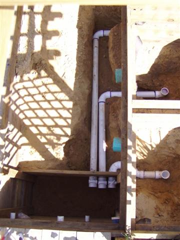
I ripped out all of the 1 1/2" drain lines in the bottom of the settling chambers and replaced them with 3". I ripped out the 55 gallon barrel, and made the pumphouse area deeper and added a 6" tile line so that I when I drain the settling chambers, they will go all the way down the hill.
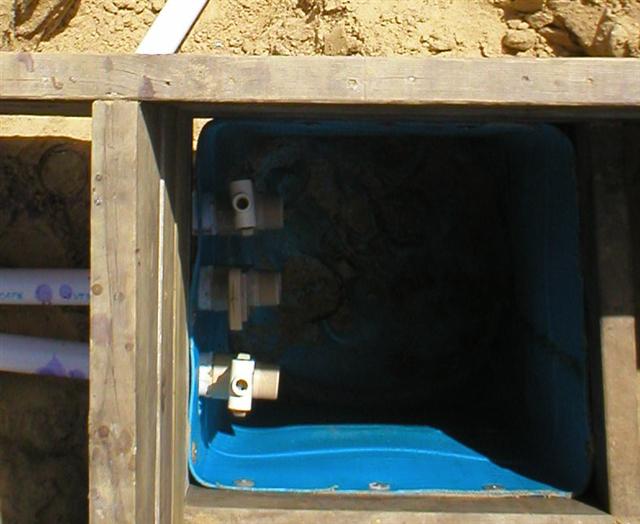
3" gate valves.
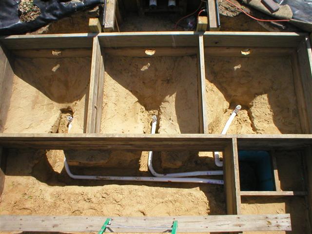
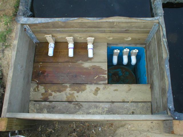
new drains in all 3 chambers.

I also added a drain line in the filter pit.
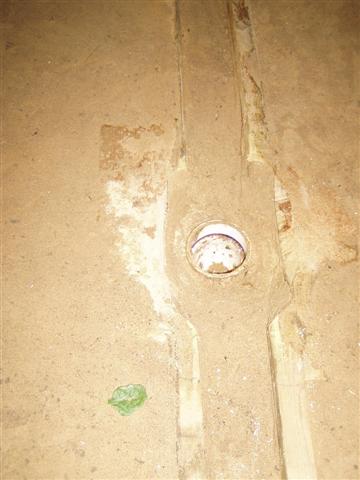
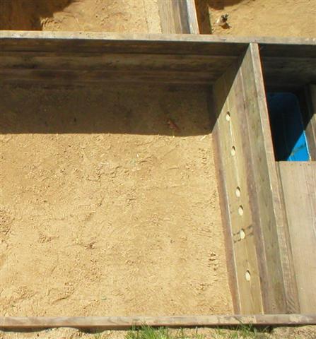
Close up of the drain in the filter pit. I used green treated wood to make a trough down the center of the filter pit.

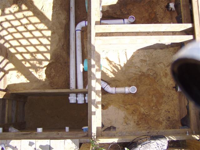
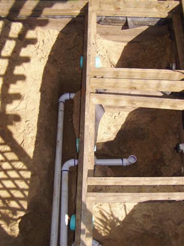
Instead of the 4" lines coming from the settling chambers on the left side I switched over to using 6" pipe coming stright through the sidewall. This will allow me to have much higher flow rate.

Four 3" gate valves total.

Rubber liner is installed, pipe boots are done.

I added milk crates full of Bickal Bio-Rope.

Bricks on top to weight it all down and hold it in place.

For Each Settling chamber, I relined them with rubber, however I also added 55 gallon barrel inside the way I do with the new Bickal Filter.

I made 8" center tubes for the barrel to connect it to the 6" line that goes into the filter chamber.

Easy Accessable Lid.
Assembly
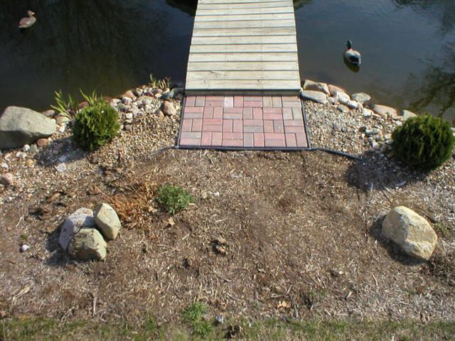
- Select a location which will be the most natural to view the pond. The site I selected will be replacing an older
pump house and settling chamber which were too small.
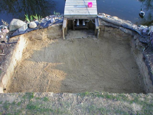
- Excavate a hole 12' wide by 8' high. The hole should be 24" deep. You should have approximately 200 cubic feet
of soil to haul away. It took me approximately 6 hours to dig this through very sandy soil.
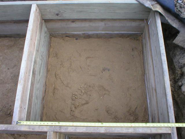
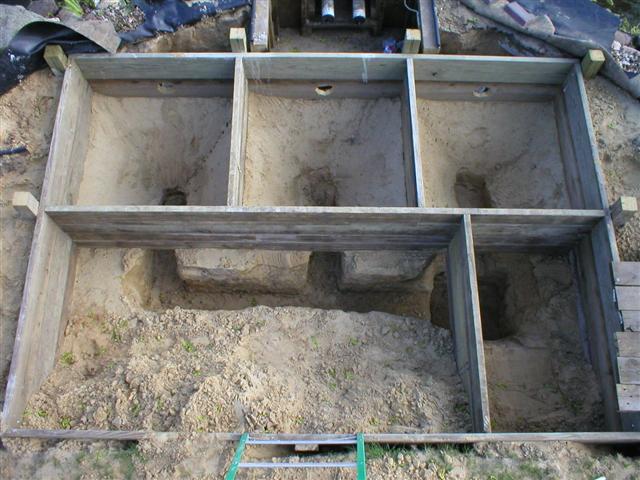
- Make a framework for the filter using the 2x6 boards. The inside dimension of the settling chambers
should be 42 5/8" square. The outside dimension of the entire filter should be 11'10" by 7'9".
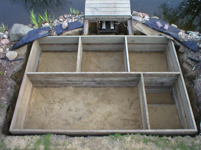
- A close-up of the filter chamber.
- A close-up of the pumphouse.

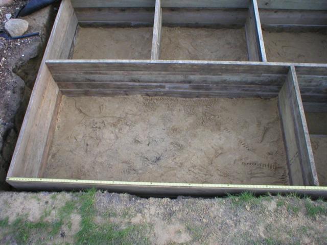
- A close-up of one of the settling chambers.
- The hole for the cement footing is dug. There are 8 of these total.
- Holes are drilled for attaching carriage bolts to the 4x4 posts.

- Carriage bolts are inserted through the 4x4 posts. The post should stick up above the framework by 5-1/2".
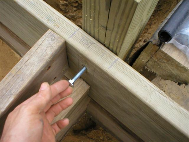
- The washer and nut are threaded on the carriage bolt.

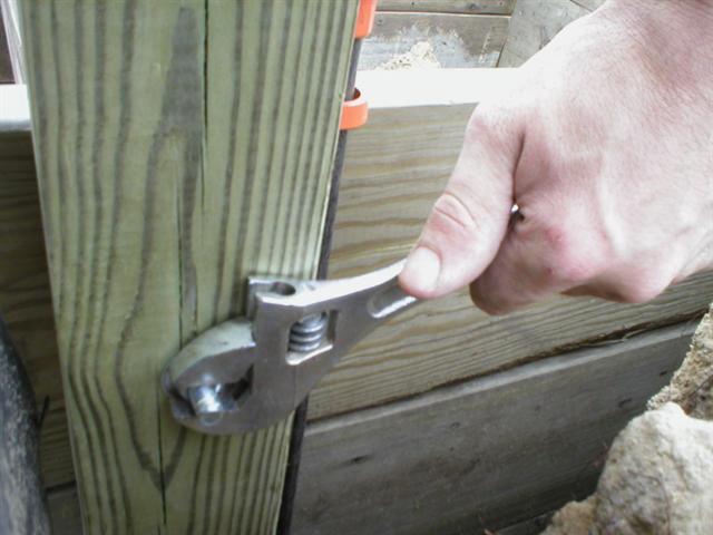
- The washer and nut are tightened on the carriage bolt.
- Due to the location of the carriage bolt, it was necessary to notch out part of the 2x6 to allow room for the
head of carriage bolt.
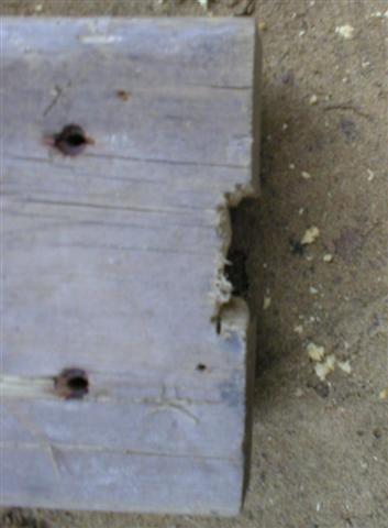
- The 2x6 is attached with the head of the carriage bolt visible in the notch.
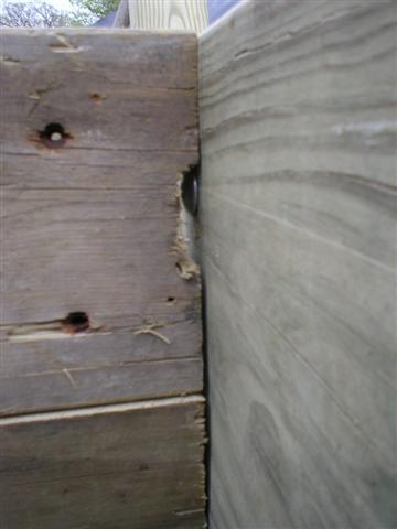
- Both the top and bottom carriage bolts are finished. The cement footings can now be poured.

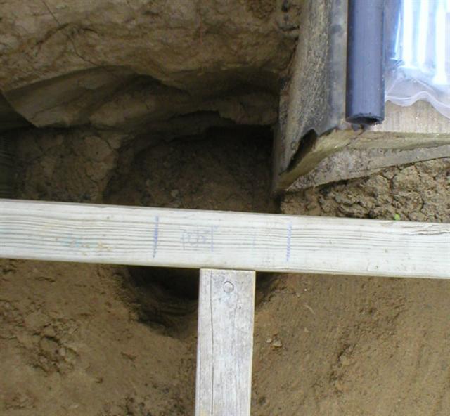
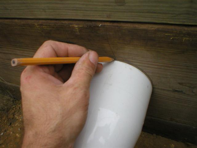
- A hole is marked in the center of 2x6 where the pipe from the bottom drains will enter the settling chamber.
A chunk of 4" pvc pipe is used as a guide. The hole should about 3" above where the settling chamber starts to taper in diameter.
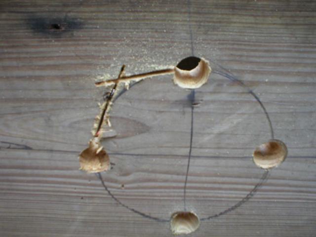
- Since most people do not have a hole saw big enough to cut the holes for the 4" pipe, I will demonstrate how to make
an octagonally shaped hole. Pilot holes are drilled at 4 locations. The holes should be large enough to accept the sawzall blade.

- A sawzall cut halfway towards the opposite hole.
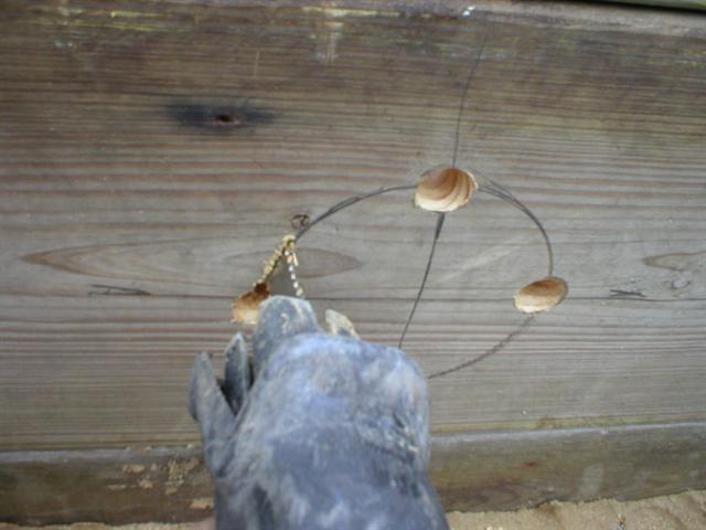
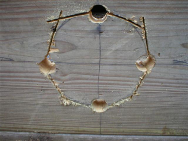
- A sawzall cut from the opposite hole towards the previous hole until the two meet.

- The 2 holes should connect.
- Repeat this process around the rest of the diameter of the hole.
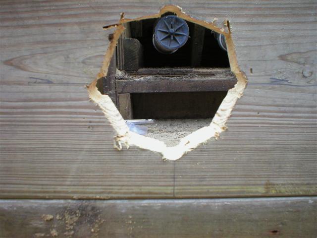
- The excess wood is removed to reviel the hole.
- Dig the settling chambers down to 39" depth. The sidewalls should be about 45 degree angle and form a square cone.

- Dig the trenches for the drain lines to the settling chambers. A hole for the barrel sump pit should also be dug.
- Install the barrel. A round barrel will work, however I wanted a square barrel to simplify the installation.
For instructions on how to make a square barrel, go here.

- 1 1/2" PVC pipe is glued into place to form the drain lines for the settling chambers. I used a heat gun to make the
large radius turns for the two chambers on the left. The 3rd chamber on the right could have entered the sump chamber
straight in, but for pure astetic reasons, I choose to have it elbow and enter with the other pipes.
- A close-up view of the settling chamber bottom. A small stub of pipe is glued to the elbow as the point where the pipe-boot

- The gate valves are installed on the drain lines in the sump pit.
- The settling chamber's are backfilled around the drain lines. There should be at least 1" of pipe exposed.

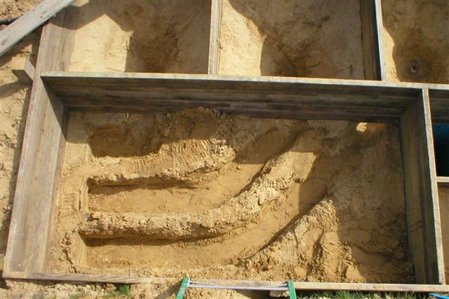
- The trenches which will take the water from the settling chambers to the filter. In this configuration all drain lines
should recieve equal flow during operation. Should there become a clog in one of the lines, the shorter of the lines would
have stronger flow. Having 3 pipes enter the filter chamber would allow for an alternate design of a segmented filter chamber if necessary in the
future (basically you could make 3 horizontal filter chambers totally independant of each other and use 3 pumps.
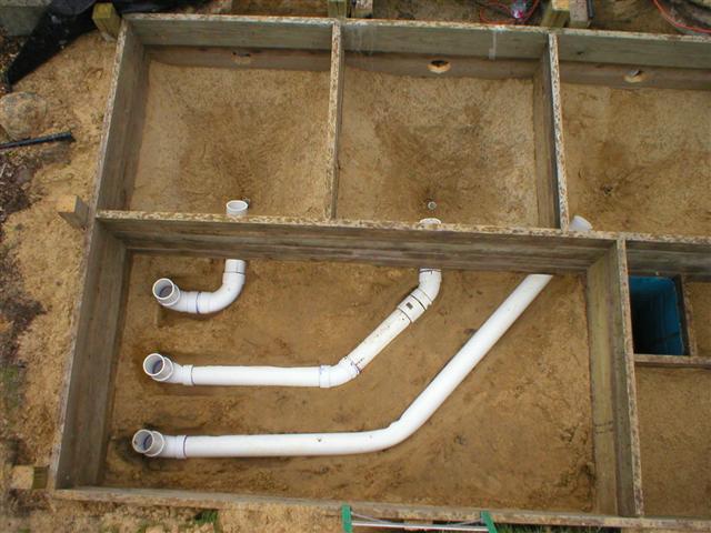
- The 4" piping is installed.
- All trenches are backfilled.

- 1 1/2" holes are drilled through the wall between the filter and the pumphouse. Multiple holes were drilled in case
future pumps were to be attached.
- The piping from the bottom drains is connected. Note: In this installation I am attaching to pre-existing bottom
drains. Only two drains were available and they were 3" drains. Elbows were necessary to change the direction and increase
the pipe size from 3" to 4". Ideal installation should use sweep 90 elbows were necessary. This is a temporary installation, and will be
corrected in 2005 when the pond is re-built and three 4" drains are installed.

- The settling chambers are now RFL (ready for liner). The water will enter the chamber from the pipe in the top, and
then flow to the filter through the pipe on the bottom. A DIY microscreen will eventually be installed on the pipe going to the
filter. The drainline is visible in the center.

- The liner is installed in the filter and the 4" pipes are connected using a pipe boot.

- Water is allowed to enter the filter through the center pipe. This is an example of how much water can flow through a 4"
pipe under gravity pressure of a difference of 24"

- Flow through all 3 pipes.

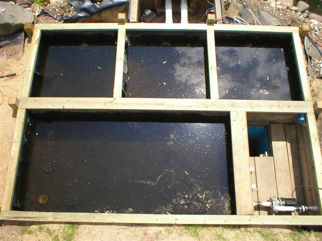
- All settling chambers and filter are filled with water. The liner is folded using the reverse hospital corners. Edges of the
liner are nailed to the wood using roofing nails and excess liner is trimmed and removed.

- A close-up of the pumphouse showing the drains and the valves which will connect to the pumps.
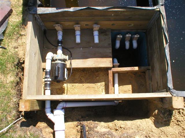
- The pump is connected (a sequence 1000, 4400gph). The pump is connected to 4" pipe to the waterfall. The line on the
lower left which goes to the sump pit is a drain line which will be used in winter to allow the water to drain so that it doesnt
freeze inside the pipe.
- The system is turned on. 3 weeks worth of gunk can be seen entering the settling chamber from the bottom drains.

- A 2x4 capping is applied to the top of the structure. This purpose is 2 fold. First to provide additional hold to keep
the rubbe in place, and second to provide ledges on which the access doors will sit.
- Floor joists are installed on the top section covering the settling chambers. This section was designed specifically
so that it would canteliever over the water. The bottom section is framed so that the sections can be removed.

- The 3 pull out sections are framed in over the filter and pumphouse.

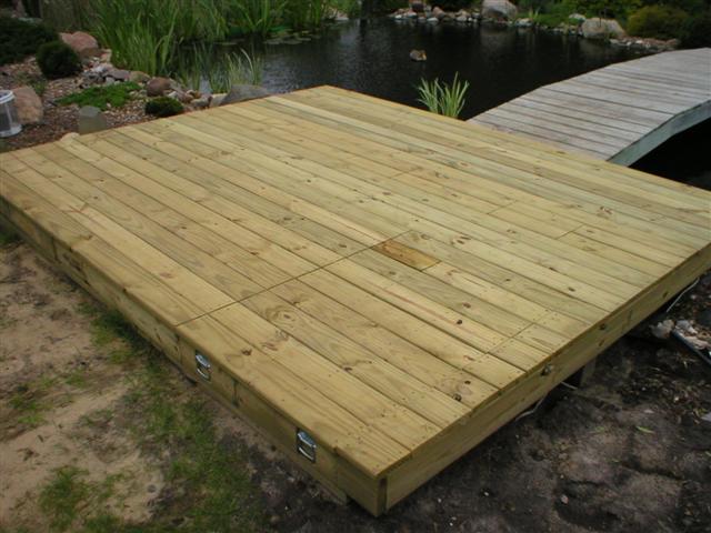
- The deckboards are installed.
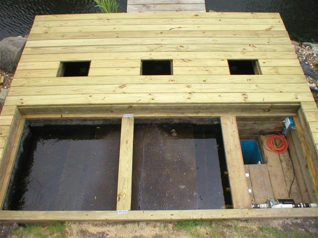
- The pull out sections are removed and the access panels to the settling chambers are removed.
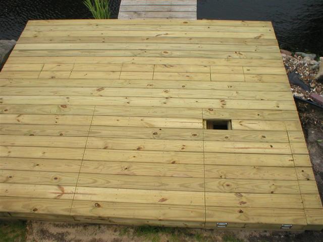
- A single access panel for the waste lines is visible. This will allow access to the valves without having to remove
the entire pannel over the pumphouse.
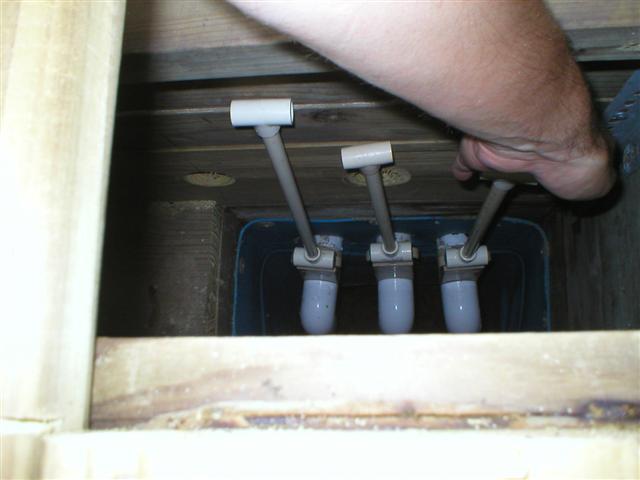
- The extension handles for the waste lines are in place.

- A view of the valves through the access panel.

- Reaching in to operate the valves.
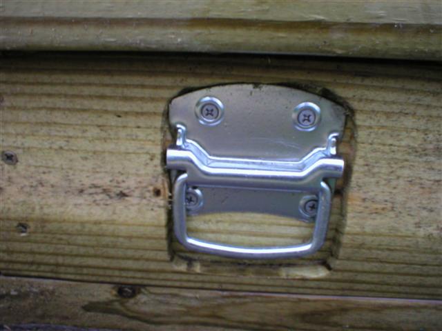
- Handles are attached to the outside of the pull out panels.

- A close-up of the handle. I used a router to recess the handle into the wood.
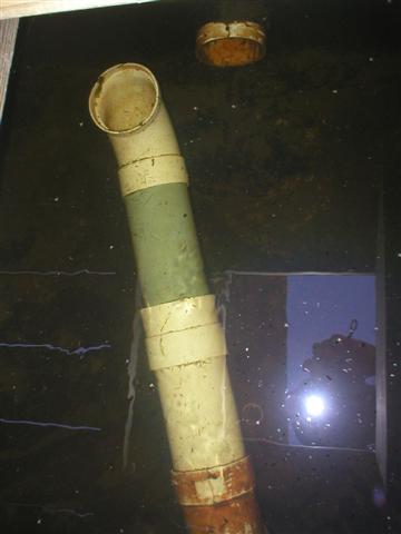
- I plan on adding Microstrainer to the settling chamber, but until I do, I added piping in the settling chamber
to move the exit pipe flow to over to the left of the water comming in from the bottom drains.
This way, the water will have to bounce off the far wall, the flow will then get split in half.
This significantly reduced the amount of debris making its way to the filter chamber.
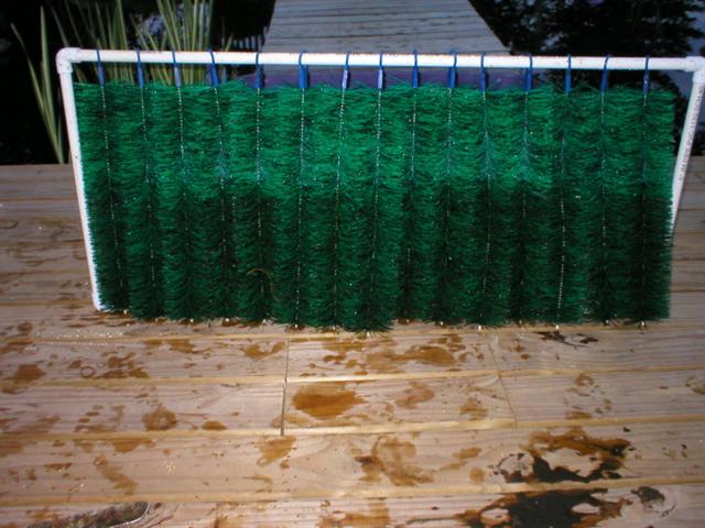
- Cutting 1/2pvc pipe to make a framework for the black night filter brushes.
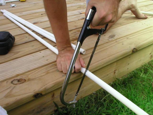
- Horizontal Pipes are just slightly smaller than the filter brushes.

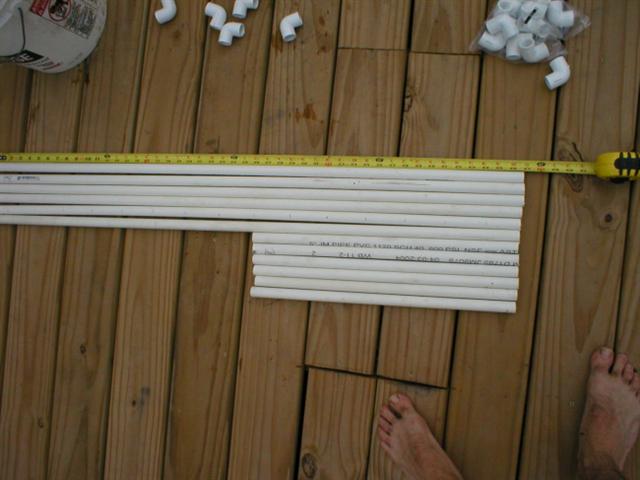
- Vertical & Horizontal Pipes are laid out for assembly
- A Frame is assembled with the brushes attached through the top loop.
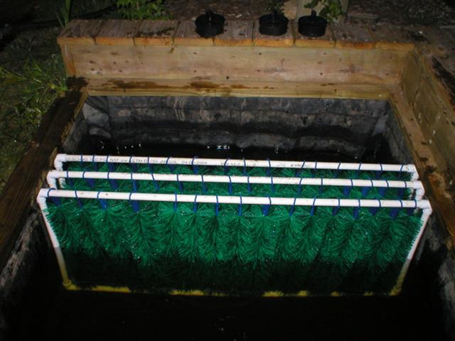
- The first set of brushes is installed in the filter.

- The Second set of brushes is installed in the filter.
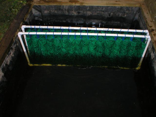
- The Third set of brushes is installed in the filter.
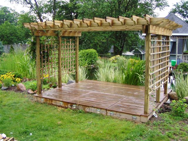
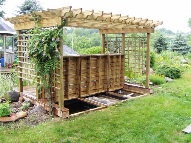
- A pergola is built over the filter as decoration.

I ripped out all of the 1 1/2" drain lines in the bottom of the settling chambers and replaced them with 3". I ripped out the 55 gallon barrel, and made the pumphouse area deeper and added a 6" tile line so that I when I drain the settling chambers, they will go all the way down the hill.
3" gate valves.
new drains in all 3 chambers.
I also added a drain line in the filter pit.
Close up of the drain in the filter pit. I used green treated wood to make a trough down the center of the filter pit.
Instead of the 4" lines coming from the settling chambers on the left side I switched over to using 6" pipe coming stright through the sidewall. This will allow me to have much higher flow rate.
Four 3" gate valves total.
Rubber liner is installed, pipe boots are done.
I added milk crates full of Bickal Bio-Rope.
Bricks on top to weight it all down and hold it in place.
For Each Settling chamber, I relined them with rubber, however I also added 55 gallon barrel inside the way I do with the new Bickal Filter.
I made 8" center tubes for the barrel to connect it to the 6" line that goes into the filter chamber.
Easy Accessable Lid.